# Object Tracking
# Introduction to object and scene tracking
Object Recognition and Tracking extend the capabilities of the Wikitude SDK to recognize and track arbitrary objects for augmented reality experiences.
Object Recognition and Tracking let you detect objects and entire scenes, that were pre-defined by you. Suitable objects include
- Toys
- Monuments and statues
- Industrial objects
- Tools
- Household supplies
Recognition works best for objects that have only a limited number of changing/dynamic parts.
# Scene tracking
The object tracking engine of the Wikitude SDK can also be used to recognize larger structures that go beyond table-sized objects. The name Scene Recognition reflects this in particular. The new image-based conversion method allows for Object targets that are a lot larger, that can be successfully recognized and tracked.
- Rooms
- Faces of buildings
- Squares and courtyards
Important: Learn how to create Object Targets
Make sure to read the chapter on how to create Object Targets before using Object Recognition on your own.
# Object tracking in Unity
Before proceeding with the Object Tracking sample, please make sure you are familiar with how Image Tracking works first by reading about the Image Tracking samples. Most concepts described there work in a similar way for Object Tracking.
To add an object tracker to the scene, simply create a new GameObject and add the ObjectTracker script to it.
An ObjectTracker itself needs a Wikitude Object Collection (.wto file) which contains information needed to detect the reference objects. Target collections can be generated and downloaded from Wikitude Studio - a free web based tool, that you can access with your developer account. You can use the .wto file in the same way as .wtc or .zip files are used for the ImageTracker.
Recognition events also work exactly like recognition events for the ImageTracker.
# Define custom augmentations
Custom augmentations are defined exactly as for an ImageTracker, so please make sure to check the chapter on Image Tracking as well.
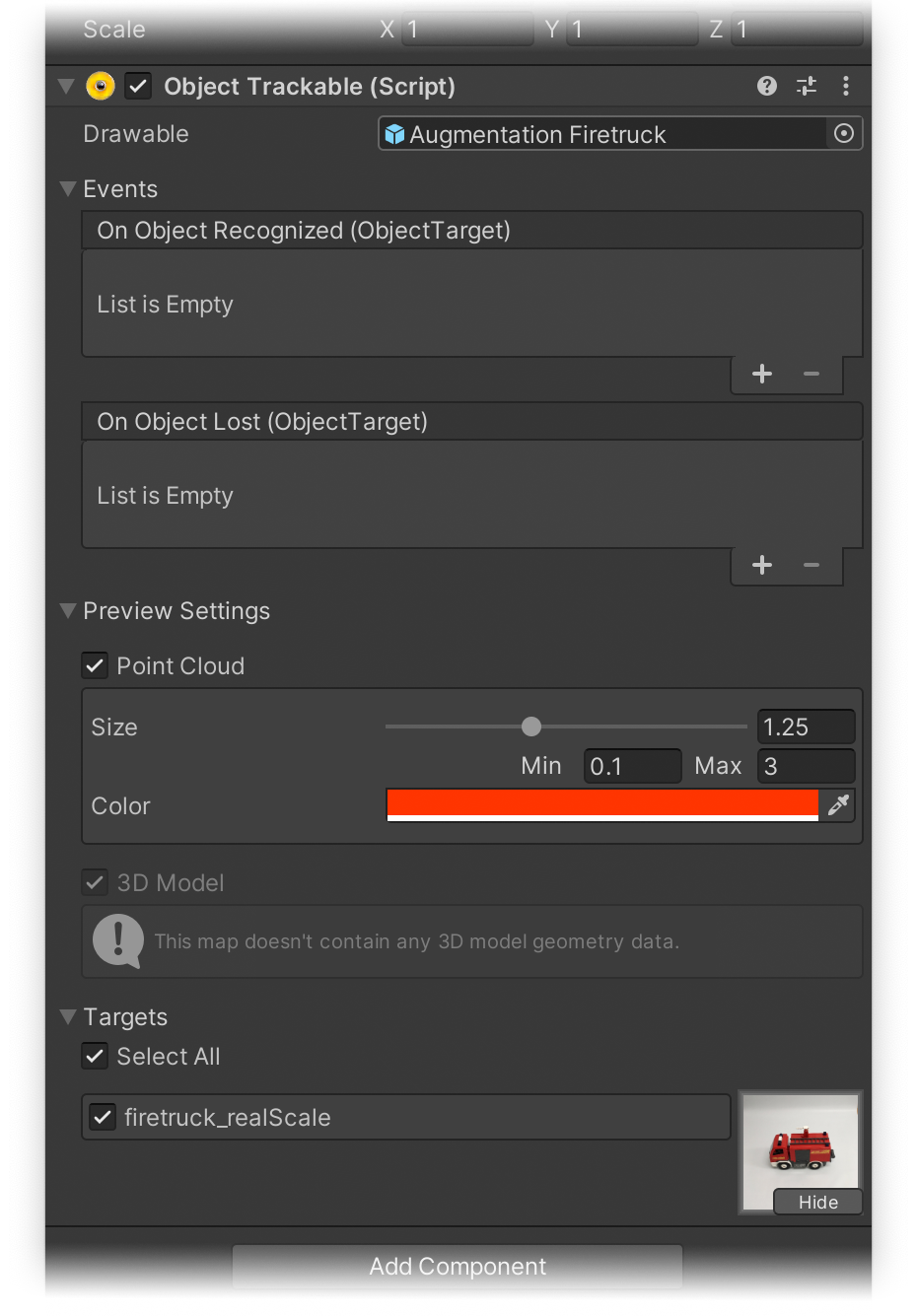
In the Simple - Object Tracking scene, the Drawable Prefab workflow is illustrated. An Augmentation Firetruck Prefab was created and assigned to the ObjectTrackable.
The transform of the Prefab has been modified so that it matches its target's preview in order for it to match the real object during tracking.
Within the Prefab you will also find the FiretruckOccluder GameObject which contains two meshes that are used as occluders. You can read more about occluders and how they work in Unity here.
During runtime, if the reference object target was found in the input camera stream, the Prefab will be instantiated and placed at its pose.
To handle visibility manually, you can subscribe to the OnObjectRecognized and OnObjectLost events on the trackable. This can be useful when you want to show different augmentations based on which target was tracked or if you want the augmentation to persist even after the target is no longer visible, if AR Bridge is used. The string parameter of these events will indicate which target was tracked or lost.
WARNING
If the .wto file you are using is not located in the StreamingAssets folder, kindly make sure that the value defined in the ObjectTrackable component's Target Pattern field corresponds to one of the target names in your target collection. You can also use wildcards to match any target or only a specific subset of targets.
If the tracker is using a .wto file located in the StreamingAssets folder, the ObjectTrackable inspector will show a list of all the targets in the .wto file. By toggling the box next to each target, you can select which ones will be tracked by this trackable, or you can choose Select All at the top to include all the targets.
# Target preview
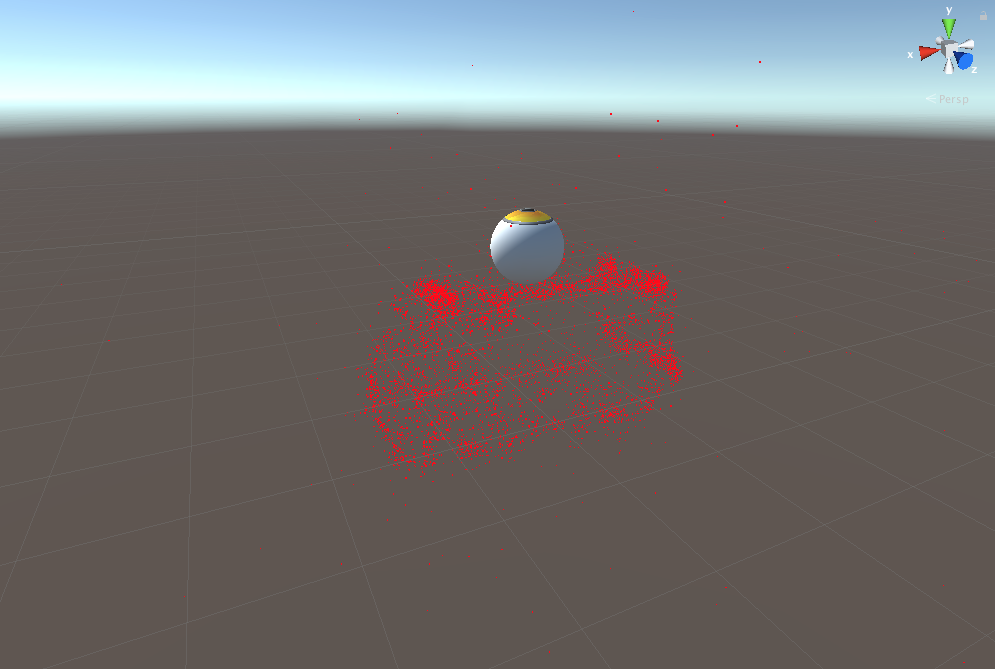
The Object Trackable also provides an option to display a preview of the target. By pressing the Preview button, the target's point cloud (if available, see object target types) will be displayed in the 3D view of the scene, providing a convenient way to place your augmentation relative to the target. You can determine the size and color of the points in the 3D representation by setting the desired values inside the Preview Settings foldout and underneath the Point Cloud toggle.
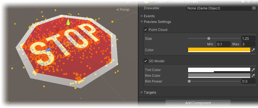
If a 3D model is included in the target collection (see object target types), options to change parameters of the preview's visualization are presented inside the Preview Settings foldout and underneath the 3D Model toggle. A target collection can also include a point cloud and a 3D model. An example of this would be the stop sign target in the Simple - Alignment Initialization sample scene.
# Multiple objects at the same time
Similar to the possibility to recognize and track multiple different images at the same time, the Wikitude SDK also supports the same functionality for objects. It's possible to add a single tracker with a combined target collection and with multiple target tracking enabled (same as with Image Targets) or use multiple trackers with single targets.
Important
Please keep in mind that each additional tracker incurs a small performance penalty, so please don't use more than are actually needed.
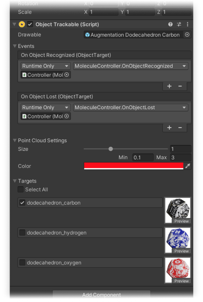
In the screenshot below, you can see how an ObjectTrackable is configured with a combined target collection.
# Runtime Tracker
Object trackers can be created at runtime with no restrictions on the location of the target collection used. To do this, simply create a new GameObject and add the ObjectTracker component to it. If you are using a collection located in the StreamingAssets folder, the TargetPath property should be the path relative to the StreamingAssets folder and UseCustomUrl property should be false.
If you want to use a collection located elsewhere on the device or on the web, the TargetPath property should be set to the absolute path to the target, prefixed by the protocol file://, http:// or https:// as appropriate. The UseCustomUrl in this case should be set to true.
Trackables can also be created at runtime, but make sure to add them as a child of the tracker before the Start() method is called on the parent tracker, otherwise they won't get registered in time.
GameObject trackerObject = new GameObject("ObjectTracker");
ObjectTracker objectTracker = trackerObject.AddComponent<ObjectTracker>();

objectTracker.TargetCollectionResource = new TargetCollectionResource();
objectTracker.TargetCollectionResource.UseCustomURL = true;
objectTracker.TargetCollectionResource.TargetPath = "https://url.to.your/collection.wto";

GameObject trackableObject = GameObject.Instantiate(TrackablePrefab);
trackableObject.transform.SetParent(objectTracker.transform, false);
# Alignment initialization
For objects that are particularly difficult to recognize automatically, the alignment initializer can be used as a way to initialize tracking for objects. How this is done in general and how the sample Alignment Initialization is implementing this, is described in the following chapter. A more formal definition of alignment initialization can be found in our section Concepts and Definitions.
Required material
The sample is using the firetruck and the stop sign objects to showcase the functionality. You can find the stop sign as printable PDF (A4 version, US letter version) and the firetruck as 360° photo in the section Targets for Testing.
To assist the SDK in finding the object, the ObjectTracker needs to be configured to use Alignment initialization in the Inspector.
Once this is done, the new ObjectTracker.UpdateAlignmentPose method can be called with a Matrix4x4 pose that provides a hint to the SDK as to where the object is located in the scene. This pose represents the relative position of the object to the camera.
Important
Alignment initialization only works on single object targets, so please make sure to only use one ObjectTracker with alignment initialization enabled at a time in your scene and that the .wto file being used only contains a single target.
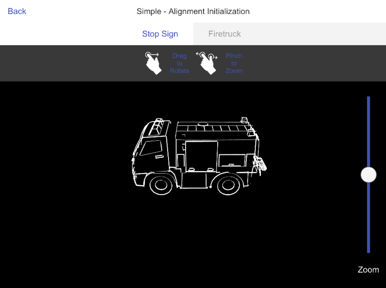
The general setup of the sample is very similar to the other object tracking samples described above, but instead of recognition working automatically, the user needs to align a silhouette of the target object with the real-world object. Please keep in mind that while the sample uses an interactive 3D model as a silhouette for the user, a simple, static 2D image can also be used as a guide, as long as the pose that is sent to the SDK matches what is being displayed.
# Scene setup
The sample scene is set up to switch between two ObjectTracker GameObjects, one with a stop sign and one with a firetruck toy target collection. The firetruck object target was created using the regular image-based generation, while the stop sign is using the 3D model based generation workflow.
More information about 3D model based generation can be found in the target management section.
The setup for alignment initialization in the sample scene consists of four parts:
- Enabling
Alignment Initializationin theObjectTrackerGameObjects as described before. - Setting the
AlignmentInteractionControllercomponent as a child of the main AR Camera. - Setting two
Alignment Drawablesfor each Object Tracker. - Configuring some assets for visualization purposes (as described in the next section).
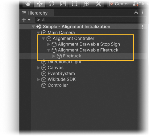
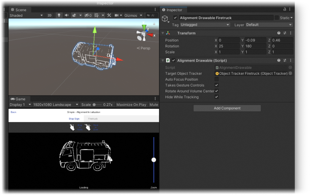
The Alignment Controller GameObject seen in the image above contains the AlignmentInteractionController component, which will manage the alignment drawable and also has some logic in place for gesture interaction.
The Alignment Drawable GameObjects each contain a component with equal name and control the relative pose of the silhouette to the camera. The user is allowed to move and rotate them and its transform will be sent every frame to the SDK as a hint of the pose to recognize.
Important
Please keep in mind that only the rotation and translation should be changed, and never the scale. To make the silhouette appear bigger or smaller on the screen, simply move it closer or farther from the camera.
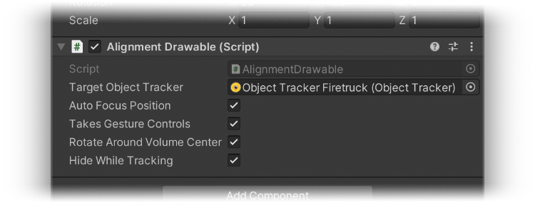
The Alignment Drawable component also comes with four toggles to modify its behaviour:
- If
Auto Focus Positionis enabled, the drawable will be automatically position at its volume center and a proper distance to the camera will be calculated. Be sure to correctly setup the drawables content first, as described in the next section. - If
Takes Gesture Controlsis enabled, the drawable will accept rotation and zoom commands coming from the gesture interaction logic of theAlignmentInteractionController. - If
Rotate Around Volume Centeris enabled, the rotation gestures will be applied on the volume center rather than the pivot of the drawable meshes. - If
Hide While Trackingis enabled, the drawables child GameObjects will be hidden upon tracking the desired target.
# Drawable alignment
To set up the Alignment Drawable GameObject, first make sure that its position is reset. Then import the assets, which should be used for alignment visualization, into the scene and parent them to the GameObject. Make sure that these assets are all aligned with the target's preview, but be sure to transform the assets and NOT the Alignment Drawable GameObject in that step.
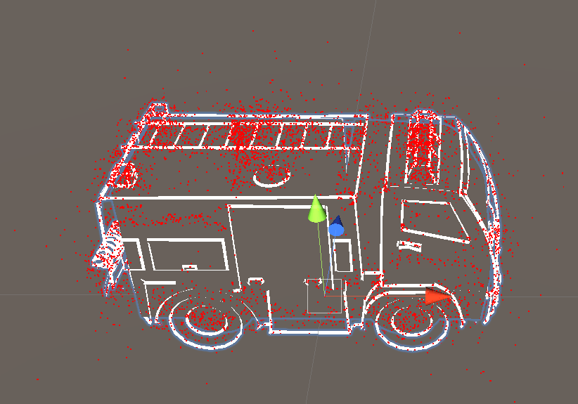
AFTER the assets are aligned with the target's preview (like seen in the image above), the initialization pose can be set by transforming the Alignment Drawable GameObject.
The position value on the z-axis for instance sets the distance to the camera. The Unity Editor's Game View should be additionally docked in the Editor to see the effects of the transformations.
Optionally, the Auto Focus Position can be enabled on the Alignment Drawable component to automatically center the assets and set their distance to the camera.
Once the scene was set up in the way described above, we just need to pass the Alignment Drawable Firetruck GameObjects transform to the SDK during runtime:
private void Update() {
    if (_recognizedTargetObject != null) {
        /* No need to send the pose if the object is being tracked */
    } else {
        /* The pose of the alignment drawable is sent to the object tracker,
         * to help it find the object in the desired pose.
         */
        var alignmentPose = Matrix4x4.TRS(transform.localPosition,
                                          transform.localRotation,
                                          transform.localScale);

        ObjectTracker.UpdateAlignmentPose(alignmentPose);
    }
}
# Runtime Tracker sample
The Unity package comes with a dedicated sample scene called Simple - Runtime Tracker to showcase runtime creation of trackers and augmentations. For a detailed description of the techniques used in this sample, such as exporting AssetBundles and dynamically loading a Tracker with a custom augmentation, please refer to the section on the Image Tracking page.
# Multiple object tracking sample
To get a better understanding of how experiences with multiple objects are made, the Multiple - Object Tracking sample scene from the Unity Plugin is described in detail in this section.
This sample scene allows recognition and tracking of up to two carbon-themed, two hydrogen-themed and two oxygen-themed dodecahedrons resembling atoms. There are five "molecules" that can be shown by combining these "atoms".
- Formaldehyde - CH2O
- Water - H2O
- Carbon dioxide - CO2
- Carbon monoxide - CO
- Molecular oxygen - O2
Note
The more objects there are tracked, the more it will impact performance, which can lead to lower framerates depending on the device.
Most of the logic is implemented in the MolceculeController.cs script. The Object Tracker registers callbacks to this script to notify if an object has been found or lost.
The found atom is then stored in a list of GameObjects. If this list is altered, a calculation is triggered to see, if there are any possible combinations. The possible combinations for molecules are stored as a string array, where each element defines a central atom and the atoms to surround it. "OHH" defines for instance an oxygen atom with two connections to water atoms.
/* An array of possible molecules with the first letter of the string being the central atom. */
private string[] _possibleMolecules = new string[]{"CHHO", "OHH", "COO", "CO", "OO"};

...

private void CalculateCombinations() {
        _possibleMoleculeCombination = "";
        _combinableAtoms = new GameObject[0];

        foreach (string molecule in _possibleMolecules) {
            string checkString = molecule;
            _combinableAtoms = new GameObject[molecule.Length];

            /* Find atoms in scene to be combined to form the molecule. */
            foreach (GameObject atom in _atomsInScene) {
                char atomChar;
                if(atom.name.Contains("dodecahedron_C")) {
                    atomChar = 'C';
                } else if (atom.name.Contains("dodecahedron_H")) {
                    atomChar = 'H';
                } else {
                    atomChar = 'O';
                }

                /* Add the atom to the combinable atoms array, if it is part of the molecule. */
                int index = checkString.IndexOf(atomChar);
                if (index >= 0) {
                    _combinableAtoms[index] = atom;
                    /* Replace found atom in the check string. */
                    checkString = checkString.Remove(index, 1).Insert(index, "X");
                }
            }

            /* Check if all atoms have been replaced in the string */
            if (checkString == new string('X', checkString.Length)) {
                /* We found our biggest possible molecule combination with the atoms in the scene. */
                _possibleMoleculeCombination = molecule;
                return;
            }

        }
    }
The CalculateCombinations method iterates through each possible molecule defined before. Since the array is also ordered from bigger molecules to smaller, the calculation will stop, if a match has been found. The atom gameobjects name contain their names from the .wto file. That is enough to differentiate between the atoms. A simple check is then applied to find a matching molecule. If a molecule is found, its descriptive name is stored in _possibleMoleculeCombination. New connections to the needed atoms starting from the central atom will be drawn in the Update method, if _possibleMoleculeCombination is set. That's where the second important controller plays a role. The ConnectionController.cs takes the transform from a central atom, the transform from the atom to be connected and the element letter (for instance "O" for oxygen).
private void CreateConnection(GameObject from, GameObject to, char element) {
    GameObject obj = Instantiate(ConnectionPrefab);

    var connection = obj.GetComponent<ConnectionController>();
    connection.From = from.transform;
    connection.To = to.transform;
    connection.SetElementLetter(element);

    _connectionsInScene.Add(connection);
}
The connection prefab itself consists of the central and the other atom's dodecahedron visualizations, a connection element and two notification billboards. There are two states for this prefab. A state, where the other atom is not correctly connected and a state, where it is. While the connection is not a "valid" link, there is a transparent connection shown to a transparent placeholder of the other atom. The position of the whole connection gameobject is set to the position of the central atom. The rotation is set to face the other atom and the rotation of the other atom is applied to the placeholder of it. The element letter which should be connected to the central atom is also shown on a billboard on top of the other atom's placeholder.
Once the other atom is in close range to the center of its placeholder, all transparent objects are replaced by silhouettes and a billboard with success notification is shown, signalling that the connection is linked. The occlusion shader of the augmentations of the atoms clear out the space of the dodecahedrons from all the white seen in the image below, resulting in the silhouette effect seen in the video.
The augmentations of the objects are fairly easy. A dodecahedron was modelled in Blender (opens new window). Afterwards, one of the faces was removed. After duplicating and shrinking the model, the normals were inverted. Finally, the two dodecahedrons were connected by connecting the edges of the missing face. This ring and the two dodecahedrons got three different materials assigned to them.
After importing this model into Unity, a quick alignment with the real object had to be done. In order to do so, the model was set as the drawable of the Object Tracker. In Play mode, the drawable was rotated to fit the real object and the transform values were copied and applied after exiting Play mode.

After applying different materials (occlusion shader for the outer dodecahedron and unlit shaders for the ring and the inner dodecahedron), the atom nucleus and electron layers were added. The atom nucleus consists of small objects in red and white (to visualize protons and neutrons), which have a simple random jitter behaviour assigned to them. Additionally, the nucleus rotates around its center giving it a nice look in total. The electron layers consist of two electrons each. A line renderer drawing their path is calculated on the play and a rotation behaviour is applied to each layer. The resulting augmentation can be seen in the video at the start of the section. The scripts, prefabs and additional files used in the sample can all be inspected and played around with in the Unity Plugin.